Multiplexer Element
This element allows you to join two data flows into a single data flow, i.e., to merge messages from two input ports into concatenated messages and send them to the output. The concatenation approach is determined by the Multiplexing rule parameter.
There are the following multiplexing rules:
- 1 to 1
- 1 to many
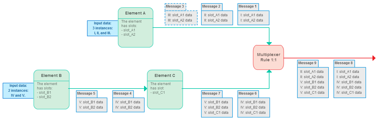
Rule: 1 to 1
This rule means that the multiplexer takes one message from the first input port and one message from the second input port, combines them into a single message, and transfers it to the output. This procedure is repeated while there are available messages in both input ports.
See an example workflow below:
As you can see:
- There are elements A, B, C, and the Multiplexer.
- A and B are data readers.
- A receives three data objects as input. These objects are denoted as I, II, and III. A has two slots; the input data objects may also contain various data. For example, these may include “Sequence” and “Set of annotations” slots, with data read from three GenBank files.
- B receives two data objects as input. These objects are denoted as IV and V. B also has two slots in this example.
- C gets messages in the workflow from B. It has one output slot. For example, this may be a “Set of annotations” slot, i.e., additional annotations were calculated for input objects IV and V.
- Now, in the Multiplexer element, we have three messages from A, corresponding to the three input objects I, II, and III. We also have two messages from B and C elements, corresponding to the two input objects IV and V with additional information calculated in C.
- The multiplexing rule is “1 to 1”, meaning we only consider messages that have a pair. Thus, “Message 3” is ignored in this case. However, the multiplexer concatenates the other messages. “Message 1” is concatenated with “Message 6”, producing “Message 8”. “Message 2” is concatenated with “Message 7”, producing “Message 9”.
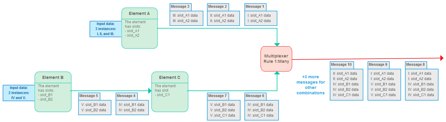
Rule: 1 to many
This rule means that the multiplexer takes one message from the first input port, joins it with each message from the second input port, and transfers the joined messages to the output. This procedure is repeated for each message from the first input port.
See an example workflow below:
As you can see, the conditions are the same as in the first “1 to 1” case described above:
- As in the first image, there are elements A, B, C, and the Multiplexer.
- A and B are data readers.
- A receives three data objects as input. These objects are denoted as I, II, and III. A has two slots.
- B receives two data objects as input. These objects are denoted as IV and V. B has two slots.
- C gets messages in the workflow from B. It has one output slot.
- The Multiplexer element receives three messages from A and two messages from C.
However, the multiplexing is done such that each message from A is concatenated with each message from C. As a result, the following messages are produced:
| Message Combination | Resulting Message |
|---|---|
| “Message 1” + “Message 6” | “Message 8” |
| “Message 1” + “Message 7” | “Message 9” |
| “Message 2” + “Message 6” | “Message 10” |
| “Message 2” + “Message 7” | “Message 11” |
| “Message 3” + “Message 6” | “Message 12” |
| “Message 3” + “Message 7” | “Message 13” |
Element type: multiplexer
Parameters
| Parameter | Description | Default value | Parameter in Workflow File | Type |
|---|---|---|---|---|
| Multiplexing rule | Available values are: 1 to 1, 1 to many. See the detailed description of the values above. | 1 to 1 | multiplexing-rule | string |
Input/Output Ports
The Multiplexer element has ports, but it has no slots.
The element has 2 input ports:
- The first input port:
- Name in GUI: First input port
- Name in Workflow File: input-data-1
- The second input port:
- Name in GUI: Second input port
- Name in Workflow File: input-data-2
The element has 1 output port:
- Name in GUI: Multiplexed output
- Name in Workflow File: output-data
Element in Samples
The element is used in the following workflow samples: